G
Guest
Guest
Well finally getting my arse in gear and sorting this amp out.
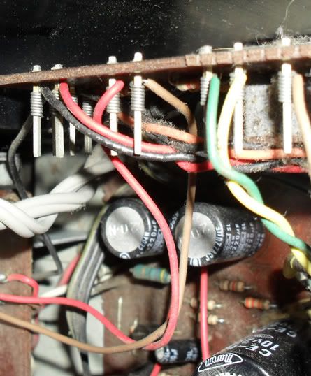
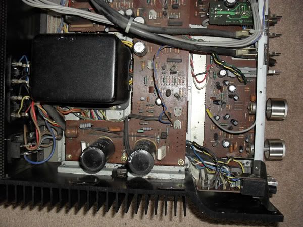
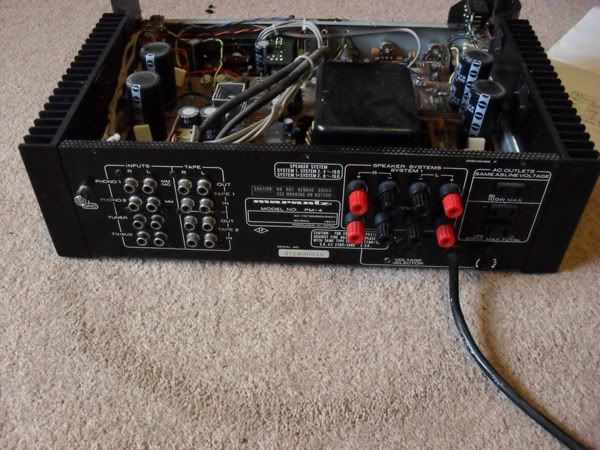
Due to age some of the big capacitors have leaked and some are just starting to bulge. So I thought I would get it sorted.
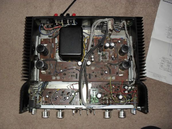
First off pictures of the inside and the bits you have to remove to open her up.
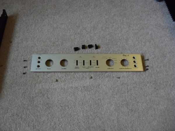
Pretty easy really. First remove the screws at the side and bottom of the front panel. Then lever off the toggle switch covers and the volume control. Then lever off the balance control. The others don't need to be removed.
The front then slides off.
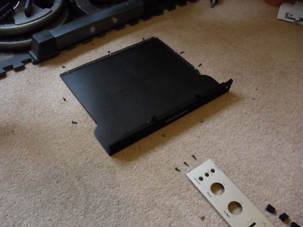
You can now start to remove the mesh cover. Do this by undoing the two newly revealed screws which where behind the front cover. Then the four screws (two each side) on the top of the heat sinks. Finally the three at the back of the mesh. It will now lift off revealing the amps internals.
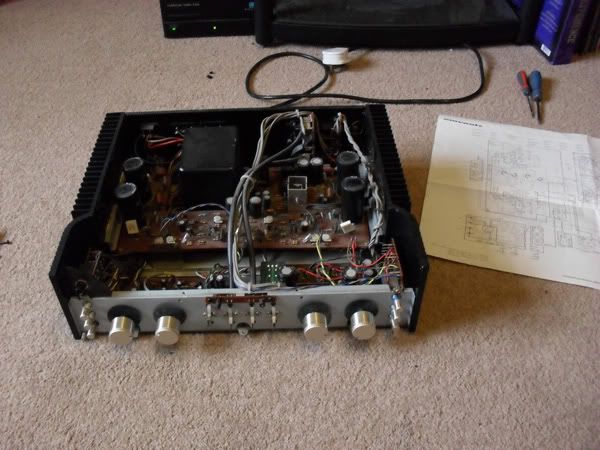
Luckily the amp I got came with the circuit diagram. Which should help.
But I have only ever built DIY kits and have never changed parts inside an old amp. So it is a bit of a mine field.
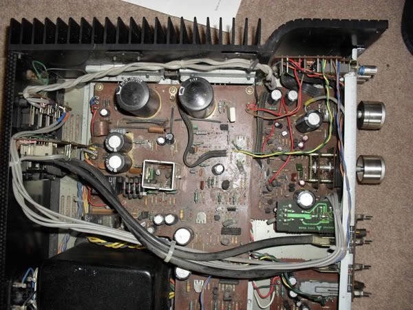
To start with I think I have identified all the electrolytic capacitors and will replace them.
Main board; 4x 55v 6800uF, 2x 16v 100uF, 2x 16v 1000uF, 2x 63v 470uF, 2x 50v 47uF, 2x 55v 220uF, 1x10v 220uF, 1x25v 100uF, 1x10v 100uF
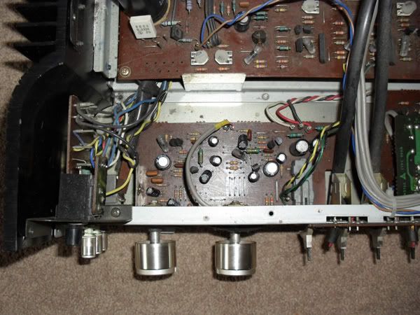
Front left;
2x 35v 100uf, 2x 25v 4.7uF, 2x 10v 100uF, 4x 10v 10uF, 2x 50v 0.22uF
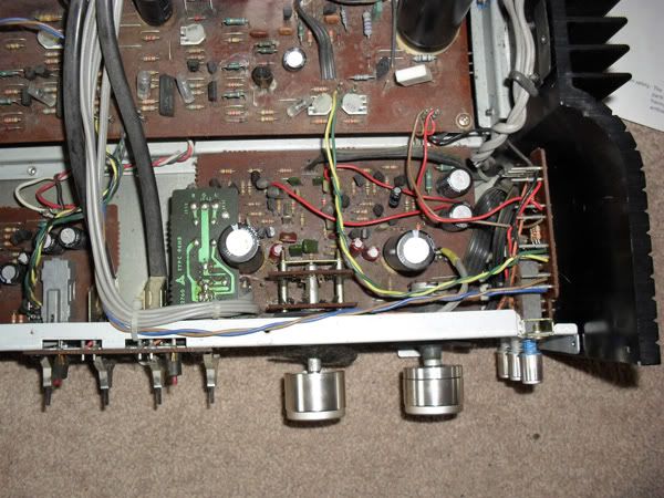
Front right;
2x 35v 220uF, 2x10v 2200uF, 2x 16v 10uF, 4x 35v 10uF
Not sure it is worth replacing the others? They shouldn't need it, I wouldn't think.
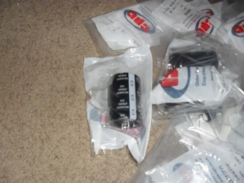
So off to order some replacements. Not looking to hot rod the amp, just replace like for like or as close as possible.
I will replace the rear screw down posts, as they are utterly useless. with any cable thicker than a human hair.
Give it a good clean/dust and probably if I ever get the time re-soldering all the boards.
Anyone know what else might need changing or is worth looking at?
Due to age some of the big capacitors have leaked and some are just starting to bulge. So I thought I would get it sorted.
First off pictures of the inside and the bits you have to remove to open her up.
Pretty easy really. First remove the screws at the side and bottom of the front panel. Then lever off the toggle switch covers and the volume control. Then lever off the balance control. The others don't need to be removed.
The front then slides off.
You can now start to remove the mesh cover. Do this by undoing the two newly revealed screws which where behind the front cover. Then the four screws (two each side) on the top of the heat sinks. Finally the three at the back of the mesh. It will now lift off revealing the amps internals.
Luckily the amp I got came with the circuit diagram. Which should help.
But I have only ever built DIY kits and have never changed parts inside an old amp. So it is a bit of a mine field.
To start with I think I have identified all the electrolytic capacitors and will replace them.
Main board; 4x 55v 6800uF, 2x 16v 100uF, 2x 16v 1000uF, 2x 63v 470uF, 2x 50v 47uF, 2x 55v 220uF, 1x10v 220uF, 1x25v 100uF, 1x10v 100uF
Front left;
2x 35v 100uf, 2x 25v 4.7uF, 2x 10v 100uF, 4x 10v 10uF, 2x 50v 0.22uF
Front right;
2x 35v 220uF, 2x10v 2200uF, 2x 16v 10uF, 4x 35v 10uF
Not sure it is worth replacing the others? They shouldn't need it, I wouldn't think.
So off to order some replacements. Not looking to hot rod the amp, just replace like for like or as close as possible.
I will replace the rear screw down posts, as they are utterly useless. with any cable thicker than a human hair.
Give it a good clean/dust and probably if I ever get the time re-soldering all the boards.
Anyone know what else might need changing or is worth looking at?