
G
Guest
Guest
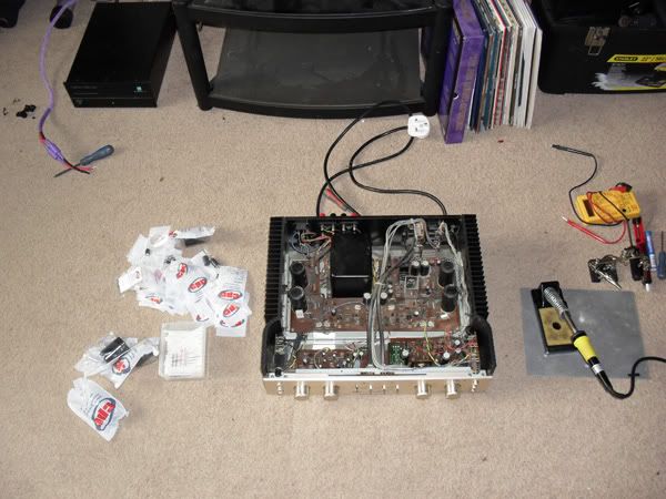
Here she is with her top off ready for work.
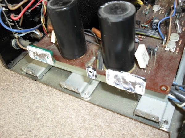
Next up off came the sides, which have hundreds of screws. Lots of old TIM that got removed, almost missed the plastic spacers. Which could have been fun!
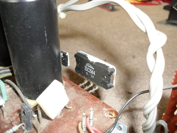
Close up of one of the chips
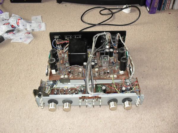
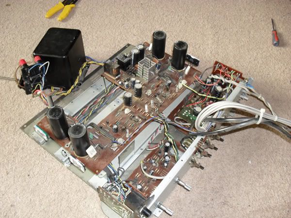
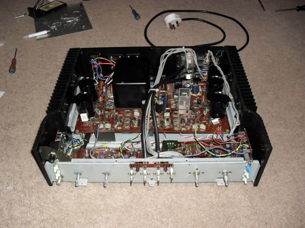
Naked!
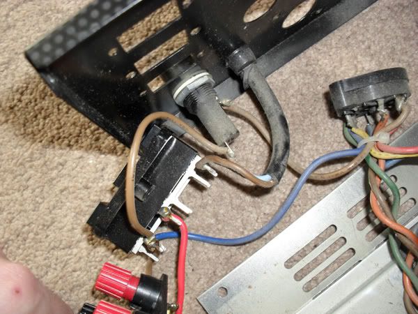
Back panel coming off, took this to remember the position of the wires.
Transformer out
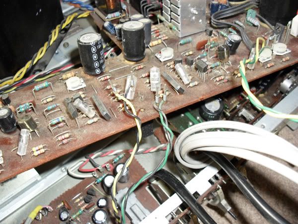
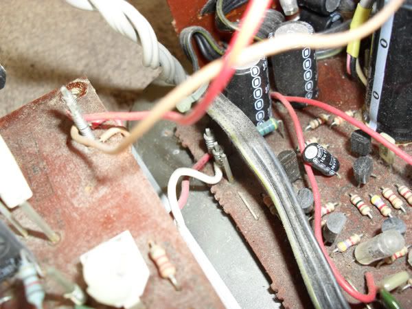
Pics of the wire wrapping so I could remember it location. Look at all that dust!
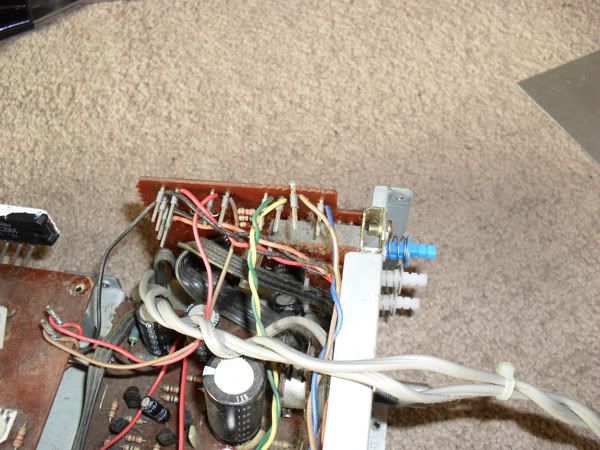
More of the above
And again
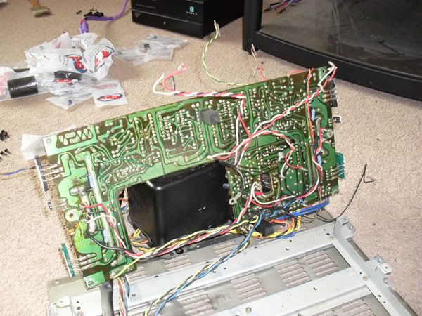
Her undercrackers
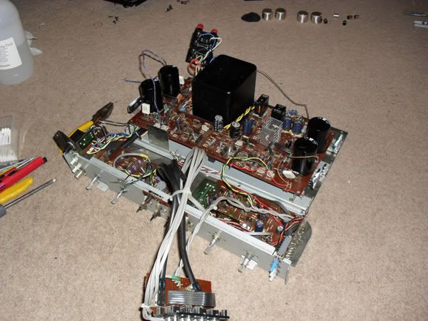
Part way through shot with most of the new bits on and some of the board cleaned.
Look at how shiny that pcb is now Lovely attention to detail on it with really good screen printing; component drawing, component number and orientation for each part.
I did take a video of turn on, just in case it blew up in a ball of flame. Since it didn't the video is pretty shite.

Next up off came the sides, which have hundreds of screws. Lots of old TIM that got removed, almost missed the plastic spacers. Which could have been fun!
Close up of one of the chips
Naked!
Back panel coming off, took this to remember the position of the wires.
Transformer out
Pics of the wire wrapping so I could remember it location. Look at all that dust!
More of the above
And again
Her undercrackers
Part way through shot with most of the new bits on and some of the board cleaned.
Look at how shiny that pcb is now
Lovely attention to detail on it with really good screen printing; component drawing, component number and orientation for each part.
I did take a video of turn on, just in case it blew up in a ball of flame. Since it didn't the video is pretty shite.